

The 555 timer has been a well-liked alternative in electronics for a very long time attributable to its versatility and wide selection of purposes.
It may be used as a timer, oscillator, frequency divider, frequency modulator, triangular sign generator, and extra.
You’ll be able to test the Attention-grabbing 555 Timer Initiatives.
The 555 timer has three primary modes: monostable, astable, and bistable.
On this article, we are going to discover a brand new mode of operation for the 555 timer that generates a singular pulse when the circuit is powered on.
Distinctive Mode of Operation for the 555 Timer
The one approach to generate one other pulse is by turning off the circuit after which powering it on once more. Whereas one may suppose that this may be achieved with the monostable mode by setting pin 2 to low (floor), doing so would consequence within the output of the 555 timer all the time being on.
(You’ll be able to do this your self)
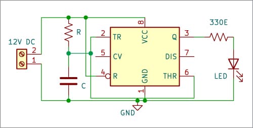
On this specific monostable mode, pins 5 and seven are usually not used. Fig. 1 illustrates the circuit diagram of this particular monostable circuit.
This new configuration of the LM555 timer in monostable mode can be utilized in varied purposes, resembling alarm techniques in automobiles, turning on a pc in a automotive, and creating an computerized dispenser for cleaning soap or antibacterial gel.
How does this Distinctive Mode Work?
To clarify the operation of this new mode, let’s seek advice from Fig. 1. When the circuit is powered on, capacitor C initially has no voltage, leading to each pin 6 and pin 2 of the 555 timer having a voltage of zero.
Within the reset comparator, the inverse enter of the comparator has a voltage of (2/3)VCC, whereas the non-inverse enter has a voltage of zero. In consequence, the interior comparator output is low.
Now, let’s think about the set comparator. Presently, the inverse enter is at 0V, and the non-inverse enter is at (1/3)VCC. Consequently, the comparator output will likely be excessive.
In conclusion, when the capacitor has some voltage, the output of the 555 timer will likely be excessive.
Whereas the capacitor is charging, the circuit continues with its output within the excessive state. The output of the 555 timer goes low solely when the voltage within the reset comparator exceeds (2/3)VCC.
When the output of the 555 timer is low, the capacitor can not discharge by way of pin 7 since this pin just isn’t used on this configuration. Thus, the 555 timer can not generate extra pulses.
Due to this fact, the one approach to generate a brand new pulse is to show off the circuit after which flip it on once more.
Computerized Dispenser Utilizing LM555
Many individuals have tried to create computerized dispensers utilizing an Arduino with an infrared module, whereas others have used simply the module itself.
Nonetheless, utilizing an Arduino Nano for this objective may be dearer than utilizing a 555 timer. Some dispensers don’t require a microcontroller or an Arduino; they work straight.
If you happen to put your hand close to the dispenser and preserve it there, the dispenser will dispense cleaning soap or gel till you take away your hand, doubtlessly leading to extra utilization.
A business computerized dispenser dispenses cleaning soap or gel for a particular period of time. Even in case you set off the sensor a number of occasions, the dispenser waits till you take away your hand from the sensor earlier than permitting you to dispense once more.
Circuit and Working
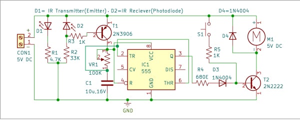
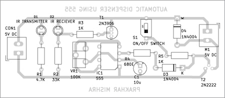
Fig. 2 presents the circuit diagram of the automated dispenser. It consists of an IR transmitter (emitter), an IR receiver (photodiode), rectifier diodes 1N4004 (D3 and D4), PNP transistor 2N3906 (T1), NPN transistor 2N2222 (T2), an LM555 (IC1), a 5V DC motor, and some different parts.
| Components Listing | |
| Semiconductors: | |
| IC1 | -555 timer |
| D1 | -IR transmitter |
| D2 | -IR receiver |
| D3-D4 | -1N4004 diode |
| T1 | –2N3906 PNP transistor |
| T2 | -2N2222 NPN transistor |
| Resistors (all 1/4-watt, ±5% carbon): | |
| R1 | -4.7-kilo-ohm |
| R2 | -33-kilo-ohm |
| R3, R5 | -1-kilo-ohm |
| R4 | -680-ohm |
| Capacitor: | |
| C1 | -10μF, 16V electrolytic |
| Miscellaneous: | |
| CON1 | -2-pin connector |
| S1 | -Pushbutton change |
| M1 | -5V DC motor |
| VR1 | -100 kilo-ohm potentiomete |
The sensor of the dispenser is a mixture of an IR emitter diode and a photodiode positioned nose to nose, so that they have a line of sight, the sunshine of the IR emitter diode we can not with eyes.
When the emitter and diode have a line of sight, the photodiode conducts power as a result of the sunshine of the emitter triggers the photodiode and when some object or a hand interrupts the road of sight, the photodiode doesn’t conduct.
The PNP transistor 2N3906 conducts solely when its base pin is at 0V or floor voltage. If it has 5V at its base, it won’t conduct.
Due to this fact, once we place our hand between the emitter and the photodiode, the bottom of the PNP transistor goes to 0V. Consequently, the output of the 555 timer at pin 3 generates a pulse, which is then despatched to transistor T2 to activate the DC motor that dispenses the cleaning soap primarily based on the time set by capacitor C1 and potentiometer VR1.
It’s vital to notice that this specific monostable mode of the 555 timer sends just one pulse. Even in case you don’t transfer your hand (obstructing the road of sight), the one manner the automated dispenser will dispense once more is by eradicating your hand, which turns off the 555 timer.
When the road of sight is obstructed once more, the dispenser will dispense cleaning soap as soon as extra.
The potentiometer on this circuit is used to regulate the shelling out time of the dispenser. We suggest a spread of 0.5 to 1.2 seconds. The exact time relies on the checks you conduct and the viscosity of the cleaning soap or gel.
Within the circuit diagram (Fig. 2), you’ll discover a push-to-on change (S1). This change is used for shelling out with out utilizing a sensor. To construct this computerized dispenser, we suggest utilizing a self-priming gear motor.
If attainable, reuse a gear motor pump from an outdated business dispenser whose digital board could have been broken.
PCB Design
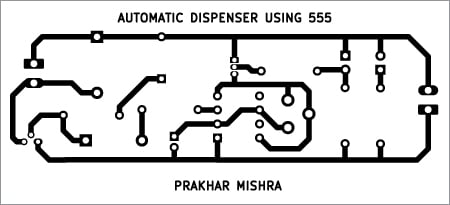
Fig. 3 reveals the actual-size, single-side PCB format for the automated dispenser utilizing the LM555. The part format may be seen in Fig. 4. After getting assembled the circuit on the PCB, enclose it in an appropriate field.
Development and Testing
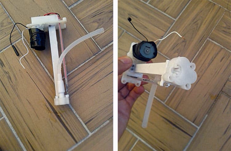
For becoming the motor with the cleaning soap disposal mechanism, seek advice from Fig. 5. Place the change in entrance of the cupboard for guide use.

Fig. 6 shows the creator’s remaining prototype, excluding the motor and cleaning soap disposal pump, which must be linked externally utilizing wires.
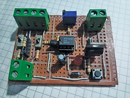
After fixing the motor as proven in Fig. 5 and assembling the parts as proven in Fig. 6, interconnect each and set up them at a correct location primarily based in your alternative.
Different DIY Dispenser Initiatives
Santiago Echeverry Serna is an digital engineer from Medellín-Colombia, who likes to experience bicycles and play basketball. He’s an electronics fanatic who likes to make easy circuits with out programming