
– Commercial –

There are a lot of AM/FM receiver circuits out there, however the tough half is making the coils and tuning the circuits. With out their correct development and alignment, the circuits don’t carry out properly. This text describes learn how to construct a easy stereo FM Radio Receiver Circuit with out tuning parts equivalent to inductors, variable capacitors, and ceramic IF filters.
Beforehand we designed the FM Receiver Circuit with tuning parts.
The FM receiver is able to receiving 76 to 108MHz FM band with stereo output having good sensitivity and efficiency. The output is able to driving a 32Ω speaker immediately, which eliminates further audio headphone amplifiers.
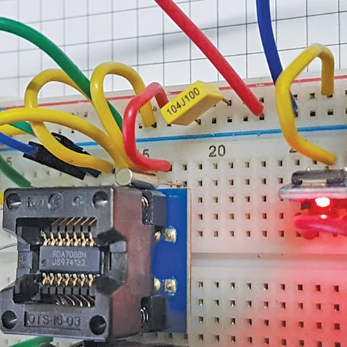
The center of the circuit is predicated on IC HEX3653/GS1299/RDA7088. We are able to use any one in all them. All three ICs have the identical pinout and performance and are available a SOP16 bundle with a 1.27mm lead pitch. You possibly can verify the RDA7088 Datasheet.
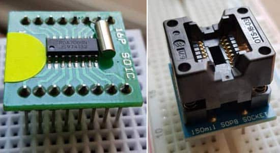
We are able to both use a pitch converter breakout board for ease of utilizing a breadboard, Veroboard, or dot board with a 2.54mm pitch. We are able to additionally use a SOIC-16 ZIF socket adaptor with a 2.54mm pitch for simple and fast experimentation.
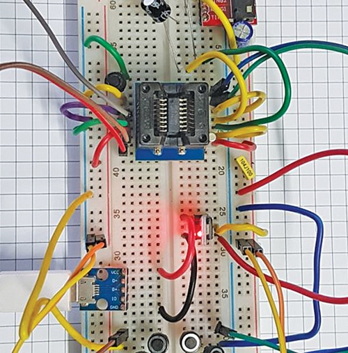
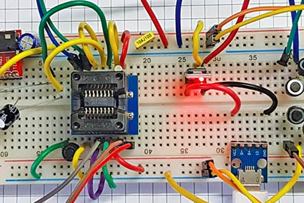
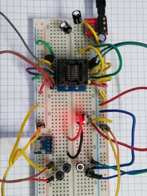
Fig. 1 reveals the Stereo FM Radio Receiver Circuit on Breadboard. The parts required to construct the radio circuit are talked about within the under desk.
| Parts Required to Construct Stereo FM Radio Receiver Circuit | ||
| Ref. | Descriptions of the parts | Qty |
| U1 | RDA7088, HEX3653, or GS1299 in SOP16 bundle | 1 |
| Y1 | 32.768kHz crystal (2mm x 6mm or 3mm x 8mm) | 1 |
| R1 | Resistor 10kΩ , 250mW (CFR 5%) | 1 |
| C3, C5 | Capacitor 100nF | 2 |
| Antenna | 75cm SWG#22 | 1 |
| C1, C2 | Capacitor electrolytic, 100µF/16V | 2 |
| L1 | Inductor 100nH | 1 |
| C6 | Capacitor 24pF | 1 |
| Breadboard or Veroboard | 1 | |
| SOP16 1.27mm to 2.54mm adaptor, or ZIF socket | 1 | |
| Jumper wires | ||
| 3V DC or AMS1117-3.3 | ||
As will be seen, the radio receiver requires only a few exterior parts, but helps the worldwide frequency band of 76 to 108MHz.
FM Radio Receiver Circuit – Options
- Lower than 5-second full band search time
- Low-cost 32.768kHz crystal for RCLK
- Digital automated achieve management (AGC)
- Direct 32Ω speaker driving
- Easy SOP16 bundle
- 1.8V to three.6V DC voltage operation
- Low present consumption of 17mA at 3V
Stereo FM Radio Receiver Circuit Diagram
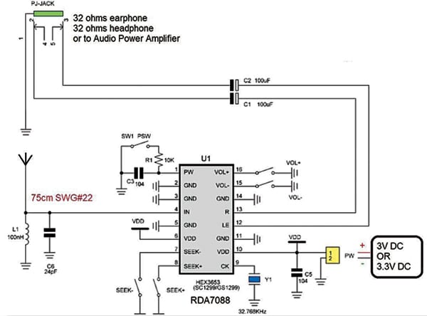
The circuit diagram of the FM Radio Receiver is proven in Fig. 3. The receiver is principally constructed across the FM RDA7088 IC together with a couple of passive parts.
Building and Testing
Assemble the circuit on Veroboard or breadboard or a general-purpose PCB. Confer with Fig. 1 by Fig. 4 earlier than meeting. First, repair the IC utilizing a 2.54mm adaptor board or ZIF SOIC-16 socket. An adaptor board requires ability to solder the 16-pin, 1.27mm pitch IC.
Join all of the GND (2, 3, 5, 11, and 14) and VDD (6 and 10) pins, as proven within the diagram. Join the 32.768kHz crystal’s one finish to pin 9 and the opposite to GND.
Join push-button switches (5 in all) to pin numbers 1, 7, 8, 15, and 16 for POWER ON/OFF, SEEK-, SEEK+, VOL-, and VOL+ capabilities, respectively. Resistor R1 (10kΩ) and capacitor C3 (100nF) are non-compulsory and never vital.
Join one finish of capacitors C1 and C2 to pin 12 and pin 13 and their different finish on to 32Ω speaker’s + terminal or to a 3.5mm audio jack for connecting an earphone or headphone of 32Ω resistance. Join capacitor C5 to pin 10 and GND.
For the antenna, join a 75cm size of SWG#22 wire to pin 4 of the IC. Inductor L1 and capacitor C6 kind the band rejector as their parallel mixture permits 76 to 108MHz band and rejects frequencies under 76MHz and above 108MHz. L1 and C6 enhance efficiency however should not necessary if availability is a matter.
Present 3V DC from two 1.5V AA-type cells linked in sequence. Make sure the polarity of the ability supply is true whereas connecting the battery to the circuit. As an alternative, you may also present 3.3V DC from a 5V adaptor. The earphone or headphone wire may work as an FM enter antenna.
Testing Circuit Features
Attempt the next capabilities to make sure that the circuit is working correctly:
- Energy on/off management utilizing SW1 (PSW) is a toggle kind enter. Urgent as soon as turns the radio on. Urgent once more turns the radio off.
- Urgent SEEK- searches the following out there channel in the direction of 76MHz.
- Urgent SEEK+ searches the following out there channel in the direction of 108MHz.
- Urgent VOL- reduces the quantity.
- Urgent VOL+ will increase the quantity.
Relying on the sign energy, the automated achieve management gives a constant efficiency with diminished noise. The general efficiency of the FM stereo receiver is nice in comparison with the price and variety of parts required.
It’s also possible to verify learn how to make a stereo amplifier circuit
Okay.N. Antony, with a B.Sc. diploma in physics and a B.Tech diploma in electronics, holds a number of US patents and is the creator of many worldwide publications, together with WIPO. His hobbies embody RF and audio amplifier design.