

Contemplating the geographical location, some areas skilled temperatures rising to 48ºC through the peak summer time season. In such conditions, a hydroponic automation system, a water-based synthetic farming setup that can be utilized largely indoors, turns into important for rising varied crops.
Nevertheless, a query arises: Is it doable to make the most of the water utilized in hydroponics for a day water bathe, scheduling it with the assistance of the Community Time Protocol (NTP)?
Moreover, can we energy the fogger setup to achieve all of the vegetation within the hydroponics system?
Right here we designed the Synthetic Plant Water Showers To Beat The Warmth!
On the finish of the article, you may examine the video to know how this method works.
The elements required to construct a hydroponic automation system are listed beneath.
| Invoice of Materials | ||
| Elements | Quantity | Description |
| ESP8266 (MOD1) | 1 | For programming |
| DHT11 (S1) | 1 | To sense atmospheric temperature and humidity |
| DS18B20 (S2) | 1 | To sense the water temperature |
| Peristaltic pump (P1) | 1 | To provide water to the fogger |
| Twin channel relay (MOD 3) | 1 | To manage the peristaltic pump |
| Water circulate valve (MOD 2) | 1 | To manage water circulate |
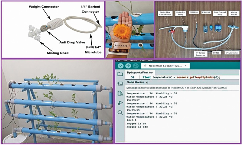
| Misting nozzle (N1) | 1 | To mistify the water for the water bathe |
| 6.4mm (¼-inch) barbed connector | 1 | To attach microtubes |
| 6.4mm (¼-inch) microtube | ¾ metre | To attach peristaltic pump with the misting nozzle and water provide |
| Jumper wires (feminine to feminine) | 9 | To attach sensors and relay |
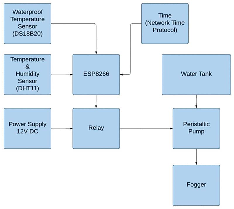
Hydroponic Automation System – Block Diagram
The bottom setup for this Hydroponic Automation challenge is positioned in room D204 of the Institute, with an approximate dimension of 9.3 sq. meters (100 sq. toes). The room is non-air-conditioned and doesn’t obtain direct daylight.
The proposed setup goals to check the feasibility of utilizing a 4-way fogger system with the help of NTP. We have now additionally carried out on-off controls for the fogger utilizing extra valves and a peristaltic pump for variable circulate management.
Fig. 1 presents the block diagram illustration of the whole setup.
Fig. 2 showcases the creator’s prototype at totally different phases. The fogger on the left-hand facet represents the commercially out there product, whereas the modified set is displayed on the right-hand facet.