ESP modules are very talked-about amongst IoT challenge builders. There are several types of esp modules accessible available in the market relying on the options. They’re ESP-01, ESP-12E, ESP-12F, NodeMCU and ESP-32. Whenever you purchase any of those modules the very first thing it’s a must to do is, make it suitable with any IDE and add a fundamental code to check it. We’re going to make the ESP-01 , NodeMCU and ESP-32 suitable with Arduino IDE and add fundamental testing codes. So lets begin.
Parts required
- ESP-01
- NodeMCU
- ESP-32
- CP2102 USB to UART bridge
- Push button
- Jumper wires (F to F) – 10pcs of various colours
All ESP boards use CP2102 UART bridge to ship or obtain knowledge from pc. The ESP-32 and NodeMCU have inbuilt CP2102 whereas for ESP-01 now we have to attach exterior CP2102 module.
The pc’s com port should additionally be capable to detect the CP2102 , for that the CP210x driver have to be put in. To put in the CP210x driver click on on this hyperlink.
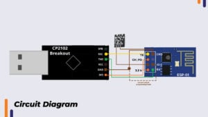
For esp-01 make the connections as per under given circuit diagram
The RXD of ESP-01 is linked to TXD of CP2102 and the TXD of ESP-01 is linked to RXD of CP2102. 3.3V from CP2102 is given to chip allow (CH_PD) pin and VCC pin of ESP module. GND from CP2102 goes to GPIO-0 , GND pin and to RST (reset) pin of esp-01 module. There’s a swap between reset and GND.
Making ESP boards suitable with Arduino IDE
To obtain Arduino IDE click on on this hyperlink. Go to obtain choices and obtain as per OS of your system . After putting in IDE, open it and observe the under given steps.
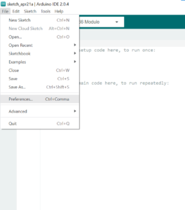
- Click on on recordsdata >> preferences
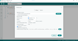
- In “Extra Boards supervisor URL’s” copy and paste the under given hyperlinks. There are two hyperlinks separated by a comma. One is for esp8266 boards and different is for esp32 boards. Copy the entire textual content given under and paste it in “Extra Boards supervisor URL’s”.
Click on on “OK”
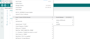
- Go to Instruments >> board >> board supervisor
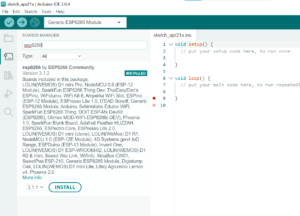
- Seek for “esp8266” and set up the “esp8266 by ESP8266 Neighborhood” package deal
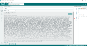
- Seek for “esp32” and set up the “esp32 by Espressif Methods” package deal.
Now now we have efficiently added the esp boards to our Arduino library.
On board led blinking check for esp-01 and NodeMCU
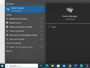
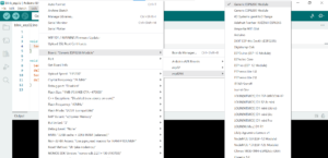
The on board led pin of ESP-01 is GPIO 1 and that of NodeMCU is GPIO 2. Earlier than writing the blinking code now we have to pick out the board and com port. The COM port quantity might be recognized by “system supervisor”. Open system supervisor in home windows.
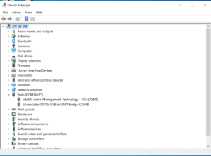
Increase the “ports” and see the com variety of CP2102 UART bridge.
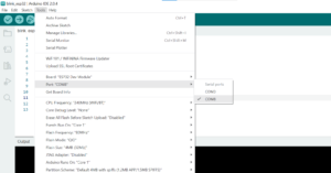
This reveals us that our ESP module is linked on COM8. Now we will open Arduino IDE and choose the board and port. Board have to be “Generic ESP8266 Module”.
Port have to be COM8 as we noticed it within the system supervisor.
Now we will add the on board led blinking code.
Code
int led = 1; // pin 1 is for esp-01 and pin 2 is for node mcu
void setup() {
pinMode(led,OUTPUT);
}
void loop() {
digitalWrite(led,HIGH);
delay(500);
digitalWrite(led,LOW);
delay(500);
}
After importing, now we have to disconnect the GND going to GPIO-0 (for the board to return out of programming mode) and press the reset button. The on-board led will begin blinking this implies the board is okay.
Now let’s check its WiFi connectivity. The on-board led will begin blinking as soon as the WiFi is linked. Enter your WiFi credentials within the code and add it.
WiFi testing code
#embody <ESP8266WiFi.h> // for ESP-32 take away ESP8266 and simply maintain it <WiFi.h>
const char* ssid = "Your WiFi ssid";
const char* password = "Your WiFi password";
int iled = 1; // for nodemcu change it to 2.
void setup() {
Serial.start(115200);
pinMode(iled,OUTPUT);
WiFi.start(ssid, password);
Serial.println("Connecting");
whereas(WiFi.standing() != WL_CONNECTED) {
digitalWrite(iled,HIGH);
delay(500);
Serial.print(".");
}
Serial.println("");
Serial.print("Related to WiFi community with IP Deal with: ");
Serial.println(WiFi.localIP());
}
void loop() {
if(WiFi.standing()== WL_CONNECTED){
digitalWrite(iled,HIGH);
delay(500);
digitalWrite(iled,LOW);
delay(500);
}
else{
Serial.println("WiFi Disconnected");
digitalWrite(iled,HIGH);
delay(500);
}
}
If the on-board led begins blinking then the ESP-01 module is getting linked to WiFi and is working.
Testing of NodeMCU
In comparable approach as we examined the ESP-01 we will check the NodeMCU. To program the NodeMCU, all you want is a micro USB cable for connecting it to the COM port. The reset button and CP2102 (USB to UART) is inbuilt.
After connecting the board to COM port. Choose the identical board kind “Generic ESP8266 Module”. Choose the port in line with system supervisor.
Led blinking code for NodeMCU is sort of identical as that of ESP-01. Simply change the on-board led pin in code from “1” to “2” for the reason that on-board led on NodeMCU is linked to GPIO-2 of NodeMCU. After importing the code the led ought to begin blinking. No have to reset as in case of the ESP-01. If the led blinks the board is okay.
WiFi testing of NodeMCU
Add the identical code as that for WiFi testing of esp-01. Simply change the on-board led pin quantity from “1” to “2”. Activate the WiFi after which add the code the led will begin blinking as quickly because the WiFi is linked. This means that the board is in good situation and is prepared for use in challenge.
Testing of ESP-32
There isn’t any on board led on ESP-32. So we’ll immediately do the Wifi check. Add the identical WiFi code as given above. Simply change the library identify from “ESP8266WiFi.h” to “WiFi.h”. Choose the board “ESP-32 dev module”. Choose the port as proven in system supervisor.
As soon as the code is uploaded open the serial monitor. If the WiFi is turned on then the WiFi linked message together with IP tackle is displayed this means that the ESP-32 board is working high-quality.
Conclusion
On this approach we made ESP boards suitable with Arduino IDE and likewise examined them. In case you have any doubt relating to any a part of this weblog you possibly can remark it, our workforce shall be there to help you.
For extra attention-grabbing initiatives take a look at our YouTube channel.


