
In This Weblog ,We Will See How a Servo Motor and Raspberry Pi Pico Used to Make a Undertaking Which Helps Out to Make Personal Servo Management System .A servo motor is utilized in purposes the place exact steering and place management is required. A servo motor has rotary encoder suggestions which permits it to lock at a particular angle. It has inbuilt gearbox which will increase the torque of the motor.
Functions Of Servo Motor
- Robotic arms – Servos are a fundamental a part of the robotic arm. It’s used to regulate the angle of the arm.
- Digital camera – Servos are used to do the auto-focusing.
- Metallic equipment – CNC and slicing machines are one of many important makes use of of servo motors.
- Distant management purposes – To actuate or rotate a mechanical half in a mannequin automobile, or airplane utilizing a distant.
There are a lot of varieties of servo motors. It relies on the applying of the person. Industrial servo motors have extra exact encoders and excessive torque functionality. For DIY initiatives, pastime servo motors are used.
Right here we’re utilizing an SG90 servo motor. The SG90 is one of the best pastime servo motor, to start with. Its torque is 2.5kg/cm and its velocity is 0.1 sec/60 levels. The working voltage is 5V.
To manage the angular place of the shaft now we have to provide a correct management sign to the orange wire. The management sign is a PWM sign. Collect the elements given within the record.
Parts record
- Raspberry pi pico
- USB cable
- SG90 servo motor
- Jumper wires (M to F) – 3ps
Join the servo motor based on below-given circuit diagram –
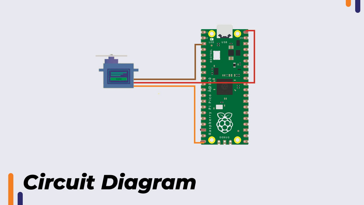
The servo motor operates on 5 volts. The servo motor will get 5V from Raspberry pi pico. The VBus pin on Raspberry Pi pico outputs 5V. The pink wire is linked to the VBus pin and the brown wire is linked to the threerd pin which is floor. The orange wire is the wire which carries the PWM sign and it’s given to PWM pin 15 of Raspberry Pi pico. All GPIO pins on Raspberry pi pico assist PWM. The servo motor may be linked to any pin.
PWM Sign For Servo Motor
In accordance with the datasheet. The PWM sign is as follows: –
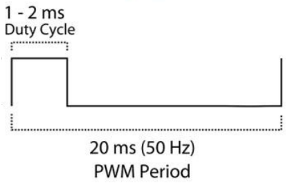
The PWM interval is 20ms. Frequency is 1/Time interval, due to this fact 1/20ms is 50Hz. We have to generate a PWM sign of 50Hz.
When the on-time is 1ms the shaft angle is at 0 levels.
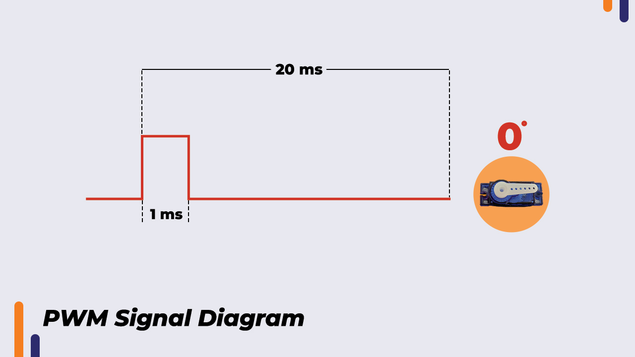
When on-time is 1.5ms the shaft angle is at 90 levels.
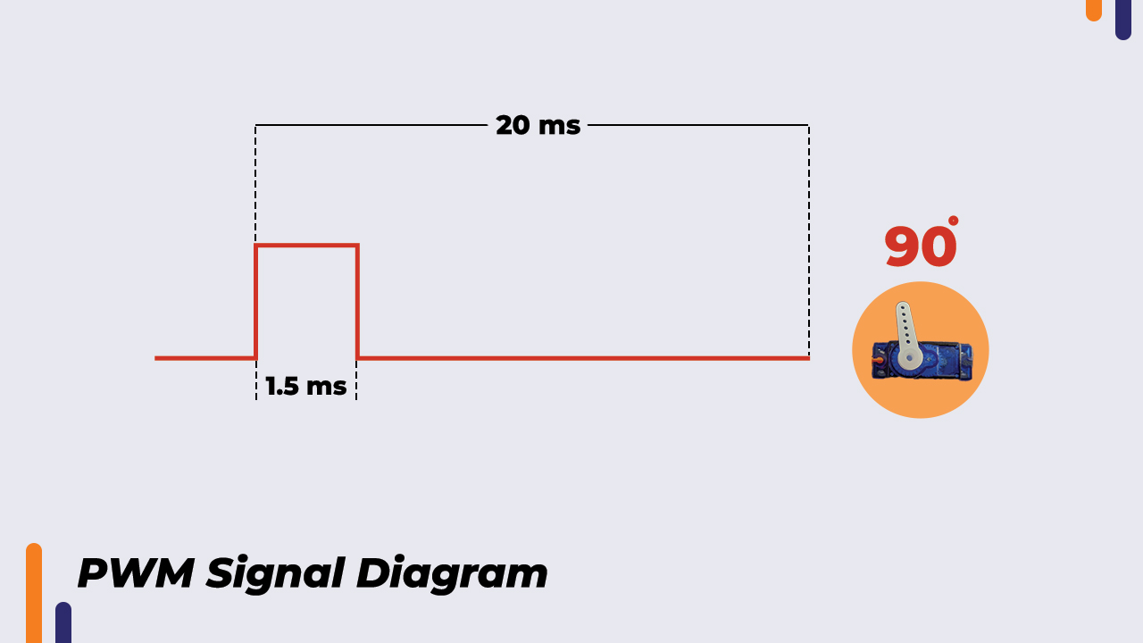
When on-time is 2ms the shaft angle is at 180 levels.

For 20ms on time the quantity to be handed within the perform “pwm. duty_u16()” is 65535. If we wish an on-time of 1ms, right here is calculation –
(65535*1ms)/20ms = 3276.75 which approximates to 3277
Subsequently, the quantity we’re going to cross in perform is 3277.
Under given is the code to generate a PWM sign of on-time 1ms and frequency 50Hz utilizing raspberry pi pico.

This code, though it’s producing on-time of 1ms. The shaft angle just isn’t 0 diploma. To get to a correct quantity comparable to 0 diploma. We should go on decreasing the quantity and add the code till we attain 0 levels angle. At 0 levels the quantity is 1800. In the same approach, I came upon for 180 levels. The quantity is 8000 for 180 levels.
Within the vary of 1800 to 8000 we get angular rotation from 0 levels to 180 levels. This implies there are 8000 – 1800 = 6200. 6200 divisions between 0 to 180 levels. Then for 1 diploma, the quantity is 6200/180= 34.45. This quantity is the fixed that we are able to use to create a perform to maneuver the servo as per angle enter.
Program with perform –

The perform accepts the angle. The angle is multiplied by 34.45 and that quantity is added to 1800. As 1800 corresponds to 0 diploma. That provides us correct quantity comparable to the angle handed within the perform. The angle quantity is saved in a variable “c” and that variable is handed within the “PWM.duty_u16()” perform which rotates the servo shaft to the specified angle.
Conclusion
On this approach, we are able to cross any angle within the vary of 0 to 180 levels in our perform and transfer the servo to desired angle utilizing raspberry pi pico. In case you have any doubt relating to any a part of this weblog then be happy to touch upon it. Our group will likely be there to help you.
For extra electronics initiatives. Try our YouTube channel